
200-301 Exam Dumps - Cisco Certified Network Associate
Searching for workable clues to ace the Cisco 200-301 Exam? You’re on the right place! ExamCert has realistic, trusted and authentic exam prep tools to help you achieve your desired credential. ExamCert’s 200-301 PDF Study Guide, Testing Engine and Exam Dumps follow a reliable exam preparation strategy, providing you the most relevant and updated study material that is crafted in an easy to learn format of questions and answers. ExamCert’s study tools aim at simplifying all complex and confusing concepts of the exam and introduce you to the real exam scenario and practice it with the help of its testing engine and real exam dumps
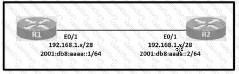
Configure IPv4 and IPv6 connectivity between two routers. For IPv4, use a /28 network from the 192.168.1.0/24 private range. For IPv6, use the first /64 subnet from the 2001:0db8:aaaa::/48 subnet.
1. Using Ethernet0/1 on routers R1 and R2, configure the next usable/28 from the 192.168.1.0/24 range. The network 192.168.1.0/28 is unavailable.
2. For the IPv4 /28 subnet, router R1 must be configured with the first usable host address.
3. For the IPv4 /28 subnet, router R2 must be configured with the last usable host address.
4. For the IPv6 /64 subnet, configure the routers with the IP addressing provided from the topology.
5. A ping must work between the routers on the IPv4 and IPv6 address ranges.
Connectivity between four routers has been established. IP connectivity must be configured in the order presented to complete the implementation. No dynamic routing protocols are included.
1. Configure static routing using host routes to establish connectivity from router R3 to the router R1 Loopback address using the source IP of 209.165.200.230.
2. Configure an IPv4 default route on router R2 destined for router R4.
3. Configure an IPv6 default router on router R2 destined for router R4.
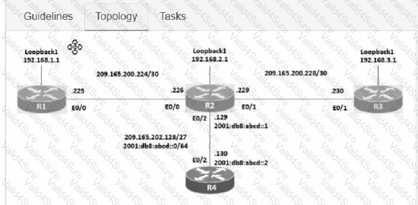
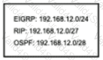
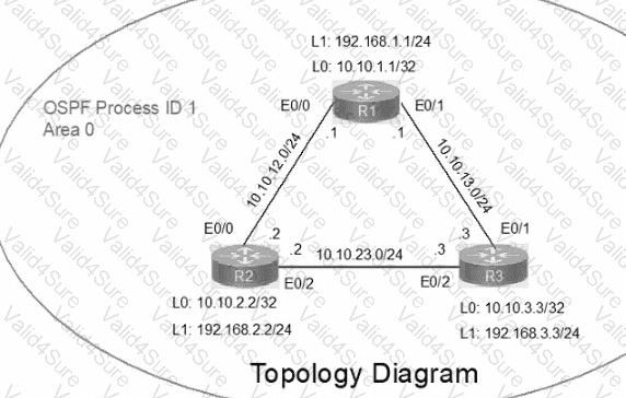
IP connectivity between the three routers is configured. OSPF adjacencies must be established.
1. Configure R1 and R2 Router IDs using the interface IP addresses from the link that is shared between them.
2. Configure the R2 links with a max value facing R1 and R3. R2 must become the DR. R1 and R3 links facing R2 must remain with the default OSPF configuration for DR election. Verify the configuration after clearing the OSPF process.
3. Using a host wildcard mask, configure all three routers to advertise their respective Loopback1 networks.
4. Configure the link between R1 and R3 to disable their ability to add other OSPF routers.
How does a switch process a frame received on Fa0/1 with the destination MAC address of 0e38.7363.657b when the table is missing the address?
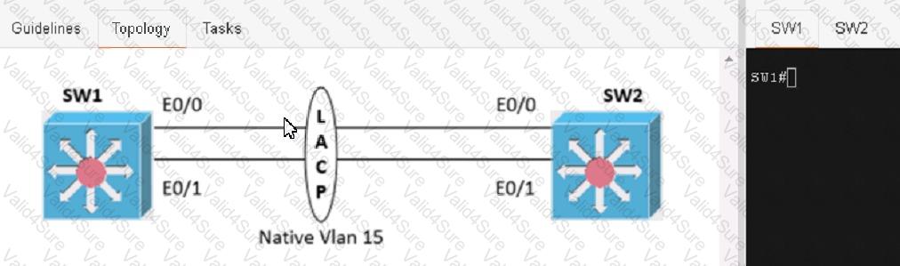
Physical connectivity is implemented between the two Layer 2 switches, and the network connectivity between them must be configured
1. Configure an LACP EtherChannel and number it as 1; configure it between switches SW1 and SVV2 using interfaces Ethernet0/0 and Ethernet0/1 on both sides. The LACP mode must match on both ends
2 Configure the EtherChannel as a trunk link.
3. Configure the trunk link with 802.1 q tags.
4. Configure the native VLAN of the EtherChannel as VLAN 15.
In which way does a spine-and-leaf architecture allow for scalability in a network when additional access ports are required?